Switched Networks
Currently many CobraNet devices are designed to allow redundant operation, such that if one device fails, another can take over for it automatically. With switched networks, redundancy is easily extended to the network. Using managed switches that incorporate spanning tree and trunking technologies, a network can automatically route data around a failed component or cut cable.
CobraNet technology for repeater networks uses broadcast packets. All the packets originating at a given device are distributed to every other device on the network. It is then the duty of the receivers to determine what, if anything, to do with each packet. Since all packets go everywhere, the maximum network capacity is determined by the sum of all the traffic on the network. Switched network support makes it possible to address packets to individual receiving devices. Intelligence in the switches means that a given device receives only those packets addressed to it. While each link between a CobraNet device and a switch still has a bandwidth limit, the total bandwidth available in the network is much larger in a switched network.
Links between switches, and between a switch and CobraNet devices, run in duplex mode. Full duplex raises the limitation of 100Mbit per link to 100Mbit each direction or 200Mbit total. Collisions are not possible if the network is constructed of switches. Network diameter limitations in repeater networks allow reliable detection and resolution of collisions. With the elimination of collisions in switched networks also comes the elimination of the network diameter issue.
Increased Reliability and Capacity
For very large systems it is possible to use Fast Ethernet switches with one or more Gigabit Ethernet ports. Each Gigabit port can carry about 1,280 audio channels over a CAT5 cable or pair of fibers to a Gigabit port on another switch. Managed switches may also be configured in several ways to increase reliability and capacity.
Spanning Tree
Normally it is illegal to wire Ethernet in a loop or ring topology. When this is done, a packet broadcast onto the network will be forwarded continuously around the loop. This condition is commonly referred to as a “broadcast storm.” Spanning tree is a protocol which allows the network to dynamically monitor its topology. If it is detected that there are multiple paths from one point on the network to another (a loop condition), one of the paths is shut down.
In addition to the convenience of not having to worry about bringing down your network through a wiring mistake that creates a loop condition, the spanning tree feature is useful for building fault tolerant networks (such as a ring topology). Spanning tree can recover from a broken network link by reactivating a redundant connection. This recovery can be accomplished in less than 30 seconds (check into Trunking and/or Meshing if your application requires faster fault recovery). Spanning tree is an IEEE standardized feature and thus a network may be built from a mixture of switches from different vendors and still utilize the spanning tree protocol.
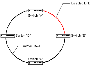
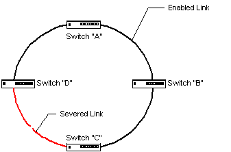
Lets look at an example using four switches. “A” connects to “D” and “B”, “B” connects to “A” and “C”, “C” connects to “B” and “D”, while “D” connects to “C” and “A”. The network automatically identifies and deactivates the redundant paths using the Spanning-Tree protocol.

If a cable between any two switches is cut, or a switch fails, disabled paths are automatically reactivated. A failed switch affects only the portion of the audio system directly connected to it.

Trunking
Trunking allows multiple connections between switches to act as a single connection. Normally a loop condition is created when multiple connections are made between switches. Trunking eliminates the loop condition by load-sharing the traffic amongst multiple links, and makes for a fault tolerant connection. If one of the connections in the trunk group should fail, the fault is routed around, almost instantly, through the remaining links.

Although the IEEE has recently developed a trunking standard (802.3ad), many manufacturers support their own proprietary Trunking protocols. To be safe, we recommended that when you plan to use the trunking feature in a design, you stick with switches from a single vendor - don’t mix and match.
Meshing
Meshing is a fusion of Trunking and Spanning Tree Protocol. Meshing is currently available in Hewlett Packard’s ProCurve switches. With meshing, switches may be interconnected in any desired topology (loops are allowed). All links remain active and load-sharing is performed. Fault recovery time is comparable to Trunking.
Multicast Filtering
Under normal circumstances, multicast addressed data consumes bandwidth on all switch ports. Multicast Filtering allows multicast data to be manually restricted to the ports that need to see it. CobraNet uses multicast addressing for clock distribution, administrative functions and, in some circumstances, audio data itself. Multicast filtering is useful in this context to eliminate the CobraNet multicast traffic from ports connected to workstations and other non-CobraNet DTEs. VLANs are another switch feature useful for segregating CobraNet and computer traffic.
VLANs
The Virtual Local Area Network (VLAN) feature allows a switch to be partitioned into non-interacting network domains. Typically, individual ports on the switch are assigned to different network domains. Uplink ports on the switch can be shared among VLANs if the switch supports the IEEE VLAN tagging scheme. Using VLANs, CobraNet traffic can be segregated from data traffic from other Ethernet applications within a facility without the need to install separate physical networks.
Quality of Service (QoS)
Quality of service features impose a priority structure on data passing through a switch. Higher priority traffic is routed through the switch more quickly and is less likely to be discarded if bandwidth capabilities are exceeded. Traffic priority can be determined by a number of factors including port assignment, DTE address, protocol type and VLAN membership. QoS can be used to give the time sensitive CobraNet data precedence over less sensitive computer traffic, insuring that other transactions occurring over the network do not affect audio delivery.
Layer 3
Some of the more advanced switches combine Ethernet switching and IP routing functions. Layer 3 refers to the OSI networking model. Ethernet and CobraNet for the most part, are Layer 2 technologies. Computer transaction and most network management functions operate at Layer 3. While switched Ethernet networks offer improved scalability over their repeater network counterparts, Layer 3 routing of data offers further scalability advantages over a Layer 2 network. Most enterprise intranets as well as the Internet itself use Layer 3 data routing. Large CobraNet installations, such as a theme park, may be built of numerous Layer 2 CobraNet networks or VLANs. The multiple networks may be interconnected at Layer 3 to allow management of all components from a central location.
Management
Management capability allows a switch to be remotely monitored and controlled. As the size and sophistication of your network grows, manageability becomes increasingly important. Most switches offering any of the advanced features described above also offer some level of manageability for the simple reason that network administrators need some means of configuring these advanced features. Most switches supporting management offer multiple ways of managing the device.
SNMP
The Simple Network Management Protocol is a widely deployed means of monitoring and controlling network components. SNMP offers the most interoperability of any management system. Very large networks may be managed uniformly through SNMP regardless of the number of different types of equipment and different manufacturers involved.
HTML
Many modern switches contain a web server. Once an address is assigned to the switch, it may be monitored and controlled remotely from a familiar web browser on a workstation.
Console
Many switches have a RS232 serial port. Management and configuration of the switch may be accomplished via the serial port before the unit is connected to the network. Console connections are often cryptic command line interfaces but are increasingly more user friendly menu systems with ASCII art.
Telnet
Telnet management allows the Console communications to be performed remotely via the network rather than through the local serial port.
For more information visit our Switched Network Examples page.
