
Network Cabling
This page is primarily targeted at audio industry professionals who may not have experience designing or installing network cable plants. It provides some quick tips and a general overview of cable plant considerations that will help lead to a high-quality network installation.
Cable Plant
A typical Ethernet network cable path is shown below. It is considered good design practice to include the intermediate patch points as shown. This gives the cable plant operator flexibility in accommodating expansion and configuration changes.
CAT5 Cabling Issues
Distance Limitations
Ethernet networks use unshielded twisted pair (UTP) Category 5 cable. CAT5 cable runs should not exceed 100 meters.
Connectors
There are two different types of RJ-45 connectors. There is the “bent tyne” connector intended for use with solid core CAT5, and then there is the “aligned tyne” connector for use with stranded CAT5 cable. Errors have popped up when using incorrect cable/connector combinations. The “bent tyne” connector will work just fine on stranded wire by the way, just not the other way around. In general, make sure your connector matches you cable type…
Twists and Terminations
When terminating CAT5 UTP cable, it is important that the natural twist of each pair be carried through as close as possible to the point of termination. EIA/TIA standard 568B requires no more than 1/2 inch be left untwisted for Category 5. More than 1/2 inch of untwisted cable will affect performance at high bit rates.
Although only 2 of the 4 twisted pairs are used for Ethernet, it is important that all pairs be terminated, and that the proper wires be twisted together. Standards set forth by EIA/TIA 568A/568B and AT&T 258A
| Pin | Signal | EIA/TIA 568A | EIA/TIA 568B | Ethernet |
|---|---|---|---|---|
| 1 | Transmit + | White/Green | White/Orange | X |
| 2 | Transmit - | Green/White or Green | Orange/White or Orange | X |
| 3 | Receive + | White/Orange | White/Green | X |
| 4 | N/A | Blue/White or Blue | Blue/White or Blue | Not Used |
| 5 | N/A | White/Blue | White/Blue | Not Used |
| 6 | Receive - | Orange/White or Orange | Green/White or Green | X |
| 7 | N/A | White/Brown | White/Brown | Not Used |
| 8 | N/A | Brown/White or Brown | Brown/White or Brown | Not Used |
CAT5 cables are typically terminated with RJ-45 connectors. Two types of RJ-45 connectors exist: the bent tyne and aligned tynes varieties. The aligned tyne version is intended for use with stranded cable. The bent tyne version, although intended for use with solid core cable, may also be used with stranded.
Straight-through vs. Crossover Cables
Two types of CAT5 cables are typically used in a network: the straight-through cable and the crossover cable. The difference between the two has to do with how the conductors terminate to the RJ-45 connector at each end of the cable. The chart below shows the RJ-45 connector “pin-outs” for CAT5 crossover and straight-through cables.
A straight-through cable is used to connect a DTE, like a CobraNet device, to a switch. The transmit pins on the CobraNet device connect directly to the receive pins on the switch and vice versa (i.e., pin 1 to pin 1, pin 2 to pin 2, pin 3 to pin 3, etc. as shown in the above graphic). Crossover cables are used to connect switches to other switches. In crossover cables, the pins are “swapped” at one end (i.e., pin 1 to pin 3, pin 2 to pin 6, pin 3 to pin1, and pin 6 to pin 2) to allow the transmit of one switch to connect to the receive of the other. Note that the same rules for crossover and straight-through cables also apply for hub-based networks.
It is very easy to tell the difference between a crossover cable and a straight-through cable by looking at the conductors in the RJ-45 connectors. If the wiring is identical at both ends, you are holding a straight-through cable, if it is different, you most likely have a crossover cable.
Crossover Cables and Uplink Ports
Some hubs and switches contain uplink ports. These ports are intended to serve as a connection to another switch or hub. As such, the uplink port is wired to use a straight-through instead of requiring a crossover cable. On some switches and hubs uplink ports share their connection with an adjacent port, so be sure to read the manufacturers instructions for proper use.
Fiber Optic Cable
General
Both single mode and multimode fiber optic cable may be used in Ethernet network designs. Although multi-mode fiber has a specific distance limitation of 2km, distance limitations of single-mode fiber vary according to the proprietary system in use. All are in excess of 2km. Single mode fiber systems tend to be more expensive than multimode systems. This is due primarily to the fact that lasers are used as light sources in single mode transceivers instead of LEDs. For this reason, it is not possible to achieve greater distance runs simply by swapping multimode for single mode fiber - the fiber transceivers must also be changed.
Remember that there is no auto-negotiation over fiber. This means that manual configuration of fiber ports is necessary to guarantee proper operation of your CobraNet network.
Connectors
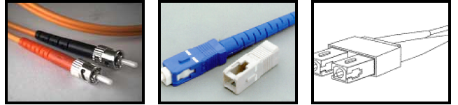
There are two common types of fiber optic connectors: SC and ST. The ST or “straight tip” connector is the most common connector used with fiber optic cable, although this is no longer the case for use with Ethernet. It is barrel shaped, similar to a BNC connector, and was developed by AT&T. A newer connector, the SC, is becoming more and more popular. It has a squared face and is thought to be easier to connect in a confined space. The SC is the connector type found on most Ethernet switch fiber modules and is the connector of choice for 100Mbit and Gigabit Ethernet. A duplex version of the SC connector is also available, which is keyed to prevent the TX and RX fibers being incorrectly connected.
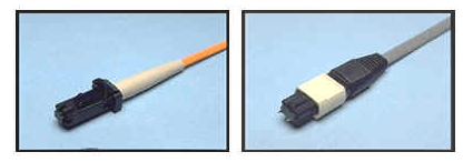
There are two more fiber connectors that we may see more of in the future. These are the MTRJ and MTP. They are both duplex connectors and are approximately the size of an RJ45 connector.
Network Performance
A number of factors can degrade the performance of your Ethernet network, and among these is a poor cable plant. Cabling problems and a susceptibility to EMI can actually lead to packet loss. Because CobraNet traffic is more sensitive to packet loss than typical datacom traffic, it is important that cable plant quality not be sacrificed. The following sections present cabling considerations that will help to ensure a high-quality cable plant installation.
Similar to audio cabling, there are certain proximity specifications to be aware of when designing your network cable routes. The following chart lists some CAT5 proximity guidelines. For fiber optic cable runs, these guidelines are no longer a concern due to fiber’s inherent immunity to EMI and RFI.
| Condition | 2kVA | 2-5kVA | >5kVA |
|---|---|---|---|
| Unshielded power lines or electrical equipment in proximity to open or non-metal pathways | 5 in. (12.7 cm) | 12 in. (30.5 cm) | 24 in. (61 cm) |
| Unshielded power lines or electrical equipment in proximity to grounded metal conduit pathway | 2.5 in. (6.4 cm) | 6 in. (15.2 cm) | 12 in. (30.5 cm) |
| Power lines enclosed in a grounded metal conduit (or equivalent shielding) in proximity to grounded metal conduit pathway | N/A | 6 in. (15.2 cm) | 12 in. (30.5 cm) |
| Transformers and electric motors | 40 in. (1.02 m) | 40 in. (1.02 m) | 40 in. (1.02 m) |
| Fluorescent lighting | 12 in. (30.5 cm) | 12 in. (30.5 cm) | 12 in. (30.5 cm) |
CAT5 and Cable Ties
Another factor that can degrade the installation quality is snug cable ties. Ties should never be pulled tight enough to deform the outer jacket of the UTP cable. Doing so produces a slight change in the cable impedance at the point under the tie, which could lead to poor network performance. If tight ties are used at even intervals down the cable length, the performance degradation is even worse. Follow the link to an article by Belden (below) for a more detailed discussion of this issue.
Pull Force and Bend Radius
A common myth is that fiber optic cable is fragile. In fact, an optical fiber has greater tensile strength than copper or steel fibers of the same diameter. It is flexible, bends easily and resists most of the corrosive elements that attack copper cable. Some optical cables can withstand pulling forces of more than 150 pounds! The fact is, Category 5 cable may be more fragile than optical cables: tight cable ties, excessive untwisting at the connector, and sharp bends can all degrade the cable’s performance until it no longer meets Category 5 performance requirements. While fiber may have a reputation for being more fragile than it really is, it still has limitations, and as such, care should be taken when installing both CAT5 and fiber optic cables. Here are some guidelines for CAT5 and fiber optic bend radius and pull force limitations:
CAT5
All UTP cables have pull force limitations much lower than those tolerated in the audio industry. If more than 25 pounds of force is applied to CAT5 cable during installation, it may no longer meet specification. Like most audio cables, UTP cables also have minimum bend radius limitations. Generic CAT5 allows a minimum bend radius of 4 times the cable diameter or 1” for a 1/4” diameter cable. Note that this is a minimum bend radius and not a minimum bend diameter.
Fiber
The bend radius and pull force limitations of fiber vary greatly based on the type and number of fibers used. If no minimum bend radius is specified, one is usually safe in assuming a minimum radius of 10 times the outside diameter of the cable. For pulling force, limitations begin at around 50 lbs and can exceed a few hundred pounds. In general, it is recommended that you check with the fiber manufacturer for specifications on the specific cable used in your installation.
Additional Resources
BiCSi (pronounced Bic See) publishes a Telecommunications Distribution Methods Manual which serves as the reference for their Registered Communications Distribution Designer Certification exam. They also Certify 3 levels of Installers. They offer training courses, videos, and books, and hold an annual convention.