Switched Network Design and Examples
Although switches provide greater benefit over repeater networks, cable distance limitations remain. Using a switched network does not change the fact that signal degradation occurs over long cable distances. Category 5 UTP cable runs are limited to 100 meters and multi-mode fiber runs longer than 2km are prohibited. Because the network diameter issue “goes away” with switched CobraNet networks, single mode fiber can now be of great benefit. Run length maximums for this medium are well in excess of multi-mode fiber’s 2km limitation.
Computing the bundle capacity of a switched network can be a more complicated affair than computing the capacity of a repeater network. One needs to consider the different types of bundles that may be used on a switched network and the number of point-to-point vs. point-to-multipoint audio connections. CobraCAD, the CobraNet network design program is a great tool that can be used to calculate bundle capacity as well as provide other CobraNet design guidance.
Integrating media converters into your switched network design requires special consideration, as not all media converters are created equal. One must also be aware of the potential for bottlenecks in an otherwise high capacity switched network. Since CobraNet is a real-time system, the network is required to deliver real-time performance.
Switched Network Examples
The following figures show some examples of typical CobraNet designs for switched networks (i.e., a network connecting CobraNet devices to switches - not hubs). For the most part, the networks shown in the Repeater Network Examples section can be done with switches - simply replace the repeater with a switch. Most of the examples shown here will illustrate situations where an advantage can be gained by using a switch rather than a repeater hub.
Switched networks require a completely different approach to network design, so when you’ve finished reviewing the examples, be sure to perform the compliancy test to determine if the switched CobraNet network you’ve designed is CobraNet compliant.
Simple Configurations
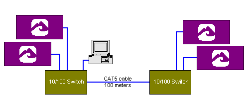
Switched networks allow control traffic (such as PCs) to live on the same network as CobraNet devices.

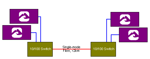
In the example below, two switches are connected via a single-mode fiber pair. Most switches provide optional fiber modules that enable fiber links to be added to the basic switch. When possible, we recommend using the fiber modules over stand-alone media converters. Be aware that the actual run length limit of single-mode fiber will depend on the fiber transceivers used.

More Complex Configurations
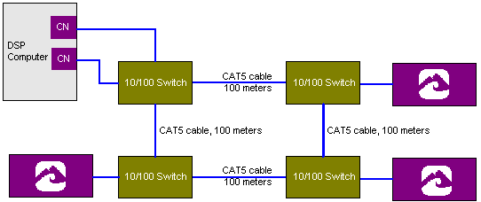
In this example Category 5 cable is used to connect four switches, each 100 meters apart. The spanning tree protocol will automatically disable one of the links in this ring to prevent a loop. (This ring configuration can only be accomplished with switches incorporating spanning tree or similar protocols.)

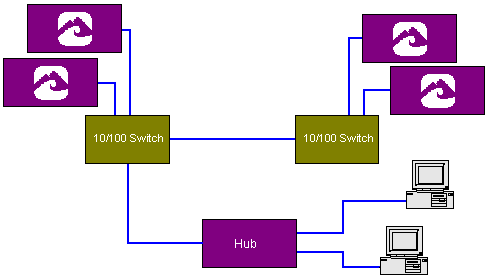
This example illustrates that it is possible to mix hubs and switches on a network. The catch: all CobraNet devices must be kept segregated from the hubs.

This example illustrates how the trunking feature (offered by some switches) can be of benefit. The bandwidth between the two switches is now doubled, and if one path is cut or damaged, the other link can still maintain the connection.

Is Your Switched Network CobraNet Compliant?
There are some basic design principals you need to be familiar with in order to build a “CobraNet-friendly” network. If you’ve read through the section on repeater networks, you’ll realize that there aren’t as many “gotchas” in switched network design. To determine whether or not your network is CobraNet compliant, read through each topic below and perform the subsequent test:
Cable Lengths
CAT5 cable runs over 100 meters are not allowed. Multimode fiber runs over 2 kilometers are not allowed. Maximum single mode fiber run lengths exceed 2 kilometers. The actual limit will depend on the fiber transceivers used.
CobraNet and Mixed Networks
The combination of repeater hubs and switches in a CobraNet network is to be discouraged. A device connected to a switched network through a hub, sees only the hub and thus operates as though on a repeater network. Timing variations through switches defeat CobraNet’s collision avoidance mechanism. See the example above for a legal way to mix switches and hubs.
Too Many Hops?
Proper operation of CobraNet hinges on basic CobraNet timing specifications. Every time an Ethernet frame (CobraNet bundle or beat packet) traverses a switch, some forwarding delay is introduced. It is important that the aggregate delay from any two points on the extremes of the network diameter not exceed the maximum allowed delay of 3.8 mS. It is also important that this delay, whatever it is, remain relatively constant within +/- 125 uS of the average value. Using a latency of 5.33 mS, a good rule is to not exceed six switch hops. The timing constraints become tighter at lower latencies and thus the number of switch hops that can be tolerated is reduced. It is best not to exceed 3 to 4 hops at 2 2/3 mS latency and to not exceed one or two hops at 1 1/3 mS latency. Observing these guidelines should yield good results in most all cases. But the actual number of hops possible can differ depending on the amount of traffic on the network and the forwarding delay characteristics of the switches used.
Help
We are more than willing to help you with your switched network designs.
